SERVFORU

Latest Post

SIMULATION OF BLOCK CODES HAMMING AND CYCLIC CODES

SIMULATION OF BLOCK CODES
AIM
To simulate linear block coding techniques for hamming and cyclic code using MATLAB.
THEORY
HAMMING CODES
Consider a family of (n,k) linear block codes that have the following parameters.
Block length,n=2m-1
No.of.message bits k=2m-m-1
No. of parity bits, n-k=m, where m>=3.
These are so called Hamming codes. To illustrate the relations between the minimum distance dmin and the structure of the parity check matrix H. Consider the codeword 0110100,In the matrix multiplication is done, and the non-zero elements of this codeword “shift” out the second, third and fifth column of the matrix if yielding. An important property of hamming codes is that they satisfy the condition. t=1.This means that hamming codes are single error correcting binary perfect codes.
CYCLIC CODES
Cyclic codes form a sub class of linear block codes.A binary code is said to be cyclic code,if it exhibits two fundamental properties.
  1. LINEARITY PROPERTY
The sum of two codeword is also a codeword.
  1. CYCLIC PROPERTY
Any cyclic shift of codeword is also called a codeword.


ALGORITHM
HAMMING CODE
STEP 1: Start the program
STEP 2: Assign the number of parity bits m=4
STEP 3: Calculate the block length n from m=2m-1
STEP 4: Assign the number of message bits k such that n-k=m so k=11
STEP 5: The hamming code is (5,11)
STEP 6: Obtain the input signal message randomly the input message is in binary format
STEP 7: The parity bits are calculated for input message taken.
STEP 8: The parity bits are appended along the message bit to form the codeword.
STEP 9: The codeword formed is transmitted through AWGN channel
STEP10: The received signal is then decoded to retrieve the message
STEP 11: The BER is calculated for the retrieved message
STEP 12: For the various values of the SNR and its corresponding BER,the graph is
Plotted.
CYCLIC CODE
STEP 1: Start the program.
STEP 2: Assign the block length n=7.
STEP 3: Assign the message bits,k=4.
STEP 4: The cyclic code is (7,4)
STEP 5:Generate the polynomial.
STEP 6: Obtain the input message randomly.
STEP 7: The input message is in binary format.
STEP 8: The codeword is formed by appending the parity bits with the message bits.
STEP 9: The parity bits are calculated from the generation polynomial.
STEP10: The codeword formed is transmitted through AWGN channel.
STEP11: The received signal is then decoded with the help of generator polynomial

      Knowledge to retrieve the message.

PROGRAM

HAMMING CODE 
####################################
clc;
clear all;
close all;
m=4;
n=2^m-1;
k=11;
berf=[];
for i=1:10
    b=0;
    for j=1:50
        msg=randint(500,k,[0,1]);
        code=encode(msg,n,k,'hamming/binary');
        t=0:0.1:10;
        snr=0;
        y=awgn(code,i);
        y(find(y>0))=1;
        y(find(y<0))=0;
        msgop=decode(y,n,k,'hamming/binary');
        [number,b1]=biterr(msgop,msg);
        b=b+b1;
    end
    berf(i)=b/50;
end
semilogy(1:10,berf);
title('performance analysis in awgn for hamming codes');
xlabel('snr(db)');
ylabel('BER');

#######################################################################
CYCLIC CODES

clc;
clear all;
close all;
n=7;
k=4;
genpoly=cyclpoly(n,k,'max');
berf=[];
for i=1:10
    b=0;
    for j=1:50
        msg=randint(500,k,[0,1]);
        code=encode(msg,n,k,'cyclic/binary',genpoly);
        t=0:0.1:10;
        snr=0;
        y=awgn(code,i);
        y(find(y>0))=1;
        y(find(y<0))=1;
        msgop=decode(y,n,k,'cyclic/binary',genpoly);
        [number,b1]=biterr(msgop,msg);
        b=b+b1;
    end
    berf(i)=b/50;
end
semilogy(1:10,berf);
title('performance analysis in awgn for cyclic codes');
xlabel ('snr (db)');
ylabel ('BER');

#########################################################

RESULT
Thus the linear block coding technique for hamming code and cyclic code has been simulated using MATLAB.
 

SIMULATION OF QUADRATURE MIRROR FILTER

SIMULATION OF QUADRATURE MIRROR FILTER
AIM:
To simulate the frequency response of quadrature mirror for a two channel filter band.
THEORY:
The QMF filter is used in the sub-band coding. This filter can be used for reducing aliasing. This is a multirate digital filter structure that employes 2 decimeter in signal synthesis section. The low pass and high pass filters in the analysis section have impulse response filters (n) and (n) respectively.
Similarly the low pass filter and high pass filters contained in the synthesis section have impulse response filters (n) and (n) respectively. To reduce aliasing the synthesis section have impulse response (n) and (n) respectively,
(ω)= (ω)
(ω)=- (ω-π)
Since (ω) and (ω)is a mirror image filters
H0(ω)=H(ω)
H1(ω)=H(ω- π)
G0(ω)=2H(ω)
This is due to the above design, aliasing effects cancels.
ALGORITHM:
1. Generate the low pass filter
2. Generate the high pass filter
3. Compute the gain response of two filters
4. Plot the gain response of two filters.


QUADRATURE MIRROR FILTER:


X(ω)


FILTER CHARACTERISTICS FOR SUB-BAND CODING


Gain
H0 (ω) H1 (ω)

PROGRAM
####################################################
clc;
clear all;

%generation of complimentary lpf
b1=fir1(50,0.5);

%generation of complimentary hpf
l=length(b1);
for k=1:l
    b2(k)=((-1)^k)*b1(k)
end

%computation of gain response of two filters
[H1Z,W]=freqZ(b1,1,256);
H1=abs(H1Z);
g1=20*log10(H1);
[H2Z,W]=freqZ(b2,1,256);
H2=abs(H2Z);
g2=20*log10(H2);

%PLOT OF GAIN RESPONSE OF TWO FILTERS
plot((W*180)/pi,g1,'-',(W*180)/pi,g2,'-');
grid on
xlabel('normalized freq');
ylabel('gain');

#############################################################

RESULT:
 Thus the frequency response of quadrature mirror filter for a two channel filter bands was simulated.


FREQUENCY HOPPING SPREAD SPECTRUM

FREQUENCY- HOP SPREAD SPECTRUM
AIM
To simulate the frequency-hop spread spectrum modulation techniques using MATLAB program and to calculate the bit error rate.
THEORY
Spread Spectrum is a means of transmission in which the data of interest occupies a bandwidth in excess of the minimum bandwidth is necessary to send the data.
The primary advantage of a spread-spectrum communication system is its ability to reject interference whether it is the unintentional interference of another user simultaneously attempting to transmit through the channel, or the intentional interference of a hostile transmitter attempting to jam transmission. Spread Spectrum modulation was originally developed for military applications where resistance to jamming is of major concern. Another application is in multi access communication in which a number of independent users are required to share a common channel without an external synchronizing mechanism. Principles of spread spectrum modulation emphasis on direct sequence and frequency hopping techniques. In a direct sequence spread spectrum technique two stages of modulations are used. First, the incoming data sequence is used to modulate a wide band code. This code transforms the narrow band data sequence into a noise-like wide band signal. The resulting wide band signal undergoes a second modulation using a phase shift keying technique.
In a frequency-hop spread spectrum technique, the spectrum of a data modulator carrier is widened by changing the carrier frequency in a pseudo random modulator manner. For their operation both of this techniques rely on the ability of a noise like spreading code called a pseudo random or pseudo noise sequence.
PN SEQUENCE
A Pseudo Noise (PN) sequence is defined as a coded sequence of 0’s & 1’s with certain autocorrelation properties. The maximum length sequence, a type of cyclic code is commonly used as a periodic PN sequence.
In case of spread spectrum a Periodic PN sequence is used with a period of N = 2m-1, where m is the length of the shift register. Such sequences have long periods and require simple instrumentation in the form of a linear feedback shift register. PN sequence may also be a periodic. Such sequence is known as Barker sequence.


FREQUENCY HOP SPREAD SPECTRUM
In a frequency-hop spread spectrum technique, the spectrum of a data modulated carrier is widened by changing the carrier frequency in a pseudo random manner. In this the carrier hops randomly from one frequency to another. There are two frequency hopping.
  1. Slow-frequency hopping
In this the symbol rate Rs is an integer multiple of the hop rate Rh. ie. Several
Symbols are transmitted on each frequency hop.
Rs = nRh
  1. Fast-frequency hopping
In this the hop rate Rh is an integer multiple of the symbol rate Rs.ie. Carrier frequency will change or hop several times during the transmission of one symbol.
Rh = nRs

ALGORITHM
  1. Generate the signal which is to be spread.
  2. Generate the PN sequence.
  3. Multiply the PN sequence with message signal.
  4. Display the pseudo sequence and frequency-hop spread sequence.

FREQUENCY HOPPING SPREAD SPECTRUM
clc;
clear all;
close all;

% Generation of bit pattern
s=round(rand(1,25));%generating 20 bits
signal=[];
carrier=[];
t=[0:2*pi/119:2*pi];
for k=1:25
if s(1,k)==0
sig=-ones(1,120);%120 minus ones for bit0
else
        sig=ones(1,120);
    end
    c=cos(t);
    carrier = [carrier c];
    signal = [signal sig];
end
subplot(4,1,1);
plot(signal);
axis([-100 3100 -1.5 1.5]);
title('|bf|it original bit sequence');

% BPSK modulation of the signal
bpsk_sig=signal.*carrier; %modulating the signal
subplot(4,1,2);
plot(bpsk_sig);
axis([-100 3100 -1.5 1.5]);
title('|bf|itbpsk modulated signal');

% Preparation of 6 new carrier frequencies
t1=[0:2*pi/9:2*pi];
t2=[0:2*pi/19:2*pi];
t3=[0:2*pi/29:2*pi];
t4=[0:2*pi/39:2*pi];
t5=[0:2*pi/59:2*pi];
t6=[0:2*pi/119:2*pi];
c1=cos(t1);
c1=[c1 c1 c1 c1 c1 c1 c1 c1 c1 c1 c1 c1];
c2=cos(t2);
c2=[c2 c2 c2 c2 c2 c2];
c3=cos(t3);
c3=[c3 c3 c3 c3];
c4=cos(t4);
c4=[c4 c4 c4];
c5=cos(t5);
c5=[c5 c5];
c6=cos(t6);
% Random frequency hops to form a spread_signal
spread_signal=[];
for n=1:25
    c=randint(1,1,[1,6]);
switch(c);
case(1)
spread_signal = [spread_signal c1];
case(2)
spread_signal = [spread_signal c2];
case(3)
spread_signal = [spread_signal c3];
case(4)
spread_signal = [spread_signal c4];
case(5)
spread_signal = [spread_signal c5];
case(6)
spread_signal = [spread_signal c6];
end
end
subplot(4,1,3);
plot(spread_signal);
axis([-100 3100 -1.5 1.5]);
title('|bf}if spread signal with 6 frequencies');

% Spreading BPSK signal into wideband with total of 12 frequencies
freq_hopped_sig = bpsk_sig.*spread_signal;
subplot(4,1,4);
plot(freq_hopped_sig);
axis([-100 3100 -1.5 1.5]);
title('|bf|if frequency hopped spread spectrum signal');

% Expressing the FFT's
figure,subplot(2,1,1);
plot([1:3000],freq_hopped_sig);
axis([-100 3100 -1.5 1.5]);
title('|bf|if frequency hopped spread spectrum signal or in fft');
subplot(2,1,2);
plot(abs(fft(freq_hopped_sig)));

################################################################################
RESULT
Thus the MATLAB programs for frequency hopping spread spectrum modulation techniques were executed and the waveforms were obtained.


DIRECT SEQUENCE SPREAD SPECTRUM


AIM
To simulate the direct sequence spread spectrum modulation techniques using MATLAB program and to calculate the bit error rate


THEORY
Spread Spectrum is a means of transmission in which the data of interest occupies a bandwidth in excess of the minimum bandwidth is necessary to send the data.
The primary advantage of a spread-spectrum communication system is its ability to reject interference whether it is the unintentional interference of another user simultaneously attempting to transmit through the channel, or the intentional interference of a hostile transmitter attempting to jam transmission.
Spread Spectrum modulation was originally developed for military applications where resistance to jamming is of major concern. Another application is in multi access communication in which a number of independent users are required to share a common channel without an external synchronizing mechanism.
Principles of spread spectrum modulation emphasis on direct sequence and frequency hopping techniques. In a direct sequence spread spectrum technique two stages of modulations are used. First, the incoming data sequence is used to modulate a wide band code. This code transforms the narrow band data sequence into a noise-like wide band signal. The resulting wide band signal undergoes a second modulation using a phase shift keying technique.
In a frequency-hop spread spectrum technique, the spectrum of a data modulator carrier is widened by changing the carrier frequency in a pseudo random modulator manner. For their operation both of this techniques rely on the ability of a noise like spreading code called a pseudo random or pseudo noise sequence.
PN SEQUENCE
A Pseudo Noise (PN) sequence is defined as a coded sequence of 0’s & 1’s with certain autocorrelation properties. The maximum length sequence, a type of cyclic code is commonly used as a periodic PN sequence.
In case of spread spectrum a Periodic PN sequence is used with a period of N = 2m-1, where m is the length of the shift register. Such sequences have long periods and require simple instrumentation in the form of a linear feedback shift register. PN sequence may also be a periodic. Such sequence is known as Barker sequence.
DIRECT SEQUENCE SPREAD SPECTRUM
The data sequence b (t) is a narrow band sequence whereas the PN sequence c(t) is a wideband sequence. The product signal m (t) i.e.b (t)*c (t) will have a spectrum that is nearly same as that of the PN sequence.
In this the PN sequence performs the role of spreading the code by multiplying the information bearing signal b (t) by the spreading code c (t). Each information bit is chopped up into a number of small time increments. This small time increment is called as chip.


ALGORITHM
  1. Generate the signal which is to be spread.
  2. Generate the PN sequence.
  3. Multiply the PN sequence with message signal.
  4. Display the pseudo sequence and frequency-hop spread sequence.


OUTPUTS:
DIRECT SEQUENCE SPREAD SPECTRUM
ORIGINAL SEQUENCE


PSEUDO RANDOM BIT SEQUENCE


DSSS SIGNAL
FFT OF DSSS SIGNAL


RESULT
Thus the MATLAB program for direct sequence spread spectrum technique was executed and the waveforms were obtained.


PROGRAM
clc;
clear all;

s=round(rand(1,20));

Pattern=[];
for i=1:20
    if(s(1,i)==1)
        SS=zeros(1,6);
    else
        SS=ones(1,6);
    end
    Pattern=[Pattern SS];
end

figure,plot(Pattern);
axis([1,120,-1,2]);
title('Original Signal');

Pr=round(rand(1,120));
figure,plot(Pr);
axis([1,120,-1,2]);
title('Pseudo Random Number');

Hopped_sig=xor(Pattern,Pr);

% Modulating Hopped Signal
DSSS_sig=[];
t=1:120;
fc=0.1;
f1=cos(2.*t.*pi.*fc);
f2=cos(2.*t.*pi.*fc+pi);

for j=1:120
if(Hopped_sig(j)==true)
    DSSS_sig=[DSSS_sig f1];
else
    DSSS_sig=[DSSS_sig f2];

end
end

figure,plot(DSSS_sig);
axis([1,1200,-1,2]);
title('DSSS Signal');

figure,plot(abs(fft(DSSS_sig)));
% axis([1,120,-1,2]);
title('FFT');


Periodogram Using Python Script

Periodogram
• Periodogram is the correct name for the
following process*:


• FFT stands for “Fast Fourier Transform”
• The FFT algorithm that can be used to
compute the
part.
• A periodogram is formed after taking the
average magnitude squared of the FFT.


Periodogram: Simple Example

1.n = integer
2.N = array of numbers from 0 to 2^n
3.x = exp(j*2*pi*f*N) + white noise
4.pg = abs(FFT)^2 / n
5.pgs = 10*log10(pg)
 

•Calculates spectrum from Real/Imag
axis, starting at 0 and rotating counter-
clockwise to 2pi (one full revolution)


LIBs NEEDED


Python
matplotlib.pyplot
scipy
numpy


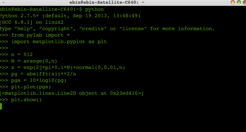
we can plot the periodagram using python using the following script


****************************************************


from pylab import *
import matplotlib.pyplot as plt
n = 512
N = arange(0,n)
x = exp(2j*pi*0.1*N)+normal(0,0.01,n)
pg = abs(fft(x))**2/n
pgs = 10*log10(pg)
plt.plot(pgs)

 plt.show()


**********************************************


Solving a Linear Systes of Equations Using python

Solving linear systems of equations is straightforward using the scipy command linalg.solve. This command expects an input matrix and a right-hand-side vector. The solution vector is then computed. An option for entering a symmetrix matrix is offered which can speed up the processing when applicable. As an example, suppose it is desired to solve the following simultaneous equations:
\begin{eqnarray*} x+3y+5z & = & 10\\ 2x+5y+z & = & 8\\ 2x+3y+8z & = & 3\end{eqnarray*}
We could find the solution vector using a matrix inverse:
\[ \left[\begin{array}{c} x\\ y\\ z\end{array}\right]=\left[\begin{array}{ccc} 1 & 3 & 5\\ 2 & 5 & 1\\ 2 & 3 & 8\end{array}\right]^{-1}\left[\begin{array}{c} 10\\ 8\\ 3\end{array}\right]=\frac{1}{25}\left[\begin{array}{c} -232\\ 129\\ 19\end{array}\right]=\left[\begin{array}{c} -9.28\\ 5.16\\ 0.76\end{array}\right].\]
However, it is better to use the linalg.solve command which can be faster and more numerically stable. In this case it however gives the same answer as shown in the following example:
>>> import numpy as np
>>> from scipy import linalg
>>> A = np.array([[1,2],[3,4]])
>>> A
array([[1, 2],
      [3, 4]])
>>> b = np.array([[5],[6]])
>>> b
array([[5],
      [6]])
>>> linalg.inv(A).dot(b) #slow
array([[-4. ],
      [ 4.5]]
>>> A.dot(linalg.inv(A).dot(b))-b #check
array([[  8.88178420e-16],
      [  2.66453526e-15]])
>>> np.linalg.solve(A,b) #fast
array([[-4. ],
      [ 4.5]])
>>> A.dot(np.linalg.solve(A,b))-b #check
array([[ 0.],
      [ 0.]])
 

How to backup your android phone using Ubuntu

Android backup 


  • If not enabled, enable developer mode by tapping Settings > About phone > Build number (7 times)
  • If not enabled, enable USB debugging in Settings > Developer options > USB debugging
  • Execute on your computer
    adb backup -apk -shared -all
This should hopefully create backup.ab with all of your apps, OS, and data. Later, after reflashing with Android (or rooting / unlocking) you will be able to use
adb restore backup.ab
to restore all of your data.
 

How to Install UBUNTU in Android Phone

Installing Ubuntu on a phone

Ubuntu 13.10 Saucy Salamander released with a new smartphone experiance . just try  it out if you have a an androind smartphone 


Instructions for flashing a phone or tablet device with Ubuntu.
After you install Ubuntu for phones, you will have the following functionality:
  1. Shell and core applications
  2. Connection to the GSM network on Galaxy Nexus and Nexus 4
  3. Phone calls and SMS on Galaxy Nexus and Nexus 4
  4. Networking via Wifi
  5. Functional camera, front and back
  6. Device accessible through the Android Developer Bridge tool (adb)


    Now it suppports only for  galaxy nexus and nexus 4 , anyway for the other phones too may be the same , we are checking with each phones ,and as no other applications are not yet available in the store

    Flashing the device

    1. Desktop setup

    The following steps are required on your desktop system in order to flash and communicate with the device.

    Setup the Ubuntu for phones tools PPA

    The PPA has the tools and dependencies to support 12.04 LTS, 12.10, 13.04 and 13.10. Add the Ubuntu for phones PPA by adding the following custom source list entry to your/etc/apt/sources.list file.
    On your computer, press Ctrl+Alt+T to start a terminal.
    sudo add-apt-repository ppa:phablet-team/tools
    
    
    Then do the following:
    sudo apt-get update 
    sudo apt-get install phablet-tools android-tools-adb android-tools-fastboot
    

    3.Device unlock

    If the device is already unlocked, skip to Step 4. These steps will wipe all personal data from the device.
    • With the device powered off, power on the device by holding the power button + volume up + volume down.
    • The device will boot into the bootloader.
    • Plug the device into the computer via the USB cable.
    • On your computer, in a terminal, run sudo fastboot oem unlock, on the device screen, accept the terms of unlocking.
    • Boot the device by pressing the power button (pointed by an arrow with Start on the screen).

    Device factory reset

    If you get stuck in a bootloop rebooting the device after unlocking the bootloader, here is what you do:
    • During the bootloop hold the power button + volume up + volume down button simultaneously to get yourself back into fastboot mode or download mode as you were previously.
    • In fastboot mode or downlaod mode, use the volume keys to scroll to Recovery and the power button to select it.
    • In Recovery (Android robot on his back with a red triangle), tap the volume up button and the power button simultaneously which will bring you into stock recovery. Don't hold the buttons, just tap them simultaneously.
    • Also make sure you're holding the correct volume button. Up will be the volume key on the right.
    • Once you're in Recovery, perform a factory reset/data wipe and then reboot your device, you should now be back to the Welcome Screen.

    4.Initial device setup

    Follow these initial steps on your device:
    1. If not booted, boot the device into Android
    2. Enable USB debugging on the device
      • On Ice Cream Sandwich (version 4.0) go to Settings and turn on USB Debugging (Settings > System > Developer options > USB debugging).
      • On Jelly Bean (versions 4.1 and 4.2) you need to enterSettings > About [Phone|Tablet] and tap the Build number 7 times to see the Developer Options.
      • On 4.2.2, (Settings > About) tap on build number 7 times to activate the developer options menu item).
      • On either Android version you must then enable USB debugging via Settings > Developer options > USB debugging. You will also need to accept a host key on the device.
        • On the workstation: adb kill-server; adb start-server
    3. Plug the device into the computer via the USB cable.
      • Depending on the installed Android version, a popup will show up on the device with the host key that needs to be accepted for the device to communicate with the workstation.
      • Note, 'adb devices' should not show the device as 'offline'. If it does, unplug the device, run adb under sudo on the workstation (egsudo adb kill-server; sudo adb start-server), then plug the device back in.
    4. Save the version of the current image on the device, if on Android, to use as a reference to revert back to. The version can be found by going to Settings > About Phone > Build Number.

    5.Downloading and deploying image to device

    1. To install Ubuntu for phones on your device, you will need to run the command:
      phablet-flash ubuntu-system --no-backup
      Please note, this will wipe the contents of the device so ensure you have made a backup.
      This will deploy the latest build onto your device, after which your device will boot into the Ubuntu Unity shell. This step can take a very long time.


How to Hard Reset and Soft Reset Nokia Asha 501

If you are thinking of sending your phone for repair, check these easy steps first. They may fix the issue and save your time and effort.
Easy fix 1: Restart your phone

Switch your phone off and take the battery out. Wait a few seconds put the battery in and switch your phone on.
Easy fix 2 : Charge your phone
Charge the battery
1. Plug the charger to a wall outlet.
2. Connect the charger to the phone.
3. When the phone indicates a full charge, disconnect the charger from the phone then from the wall outlet.
If the battery is completely discharged it may take several minutes before the charging indicator is shown or before you can make any calls.
If the battery has not been used for a long time, to begin charging you may need to connect the charger then disconnect and reconnect it.
Easy fix 3: Restore to factory settings
Restore original settings: If your phone is not working properly you can reset some settings to their original values. This does not affect documents or files stored on your phone but we recommend you take a back-up before restoring to factory settings. See instructions in the user manual.
1. End all calls and connections.
2. Select: Menu > Settings and Restore factory sett. > Settings only.
3. Type in the security code.
After restoring the original settings your phone switches off and then on again. This may take longer than usual.


IF the above 3 doesnt work go for 

1.- Basic Reset or Soft Reset Nokia Asha 501

This option restores the .ini files from the ROM.
Does not erase data (photos, videos, documents) or applications from a third party. Key Code *# 7780 # (click this combination of keys on the keyboard in the mobile)

2.- Total Reset or Hard Reset Nokia Asha 501

This option restores the original operating system from the ROM.
Formats the C: partition and deletes all data including the memory card. Key Code *#7370# (click this combination of keys on the keyboard in the mobile)


How to unlock Nokia Asha 501 by code ?

Unlocking Nokia Asha 501 by code is very easy, it is also safest and non-invasive method of unlocking your phone. To get code for unlock Nokia Asha 501 You need to provide IMEI number of Your Nokia. Type on keyboard *#06# or remove battery from Your Nokia Asha 501 to check IMEI number. IMEI is written on the information label as shown in this picture.

To unlock Nokia is required choosing network where phone was purchased. You need to also type correct IMEI of Your phone.
Selecting the correct network and the country is very important. By choosing wrong network You will risk receiving wrong unlock code.

How to enter code in Nokia Asha 501 ?
If we have blocked counter we need to enter code or reset counter using USB cable by program below


How to enter Unlock code RESET COUNTER to nokia using USB cable

Code #pw+123456789012345+1# type in the following way:
1. Turn on the phone without sim card
2. Select character # on the keypad
3. Characters p, w, + get by choosing few times STAR *
4. Press # button to approve code
5. Message "SIM restriction OFF" appears, Your phone is now unlocked

WARNING!!!
You have only 3 attempts to enter the code. The last failed attempt will block the counter.
 
 
Support : Ebin EPhrem | Ebin Ephrem | #Gabbarism
Copyright © 2011. Services | Embedded Support | Reviews | Virtual Technologys - All Rights Reserved
Template Created by ebinephrem.com Published by Ebin Ephrem
Proudly powered by Blogger