SERVFORU

How to Set Up a Timer in PIC16F877A


We have Three Timers in PIC16F877A , and here we have a look to how to setup the TIMER0 in PIC16F877A using HiTech C programm 


• To set up the timer, one must first disable interrupts so that an interrupt doesn’t occur when the timer expires.
• Then, enable the timer and assign the prescaler to the timer.
• Establish the prescaler value, and finally, load the timer register.
 Whenever the timer expires, the T0IF bit in the INTCON register will be set.
• We must clear this bit, reload the timer register, and then execute the code that is to be done at this time.

In code, the setup portion might look something like:
########################## IN ASSEMBLY PROGRAM ###########################
banksel INTCON
bcf INTCON,T0IE ; Mask timer interrupt
banksel OPTION_REG
bcf OPTION_REG,T0CS ; Enable timer
bcf OPTION_REG,PSA ; Prescaler to timer
bcf OPTION_REG,PS2 ; \
bsf OPTION_REG,PS1 ; >- 1:16 prescale
bsf OPTION_REG,PS0 ; /
movlw D’100’ ; Timer will count
movwf TMR0 ; 156 (256-100) counts

######################## IN HITECH C PROGRAM #######################################
OPTION_REG= 0x0F;
  TMR0=0x0F;
  while(TMR0IF=0);
  TMR0IF=0;
##################################################

• Clearly, the individual bits in the option register could all be set with a single store.
• If we didn’t care about the RB0 interrupt, the weak pullups, or the transition of RA4, then instead of five bit manipulations we could have said:
• movlw B’10000011’ ; Set up prescaler and
• movwf OPTION_REG ; timer

The execution loop might look something like:


main:
    btfss INTCON,T0IF ; Did timer overflow?
    goto main ; No, hang around some more 
    movlw D’100’ ; Timer will count
    movwf TMR0 ; 156 (256-100) counts
    bcf INTCON,T0IF ; reset overflow flag
    call DoCode ; Execute main code
    goto main ; Go back and wait


Using Timers in PIC16F877A


A timer counts pulses of a fixed, known frequency usually the system clock for the processor.Physically, timer is a register whose value is continually increasing to 255, and then it starts all over again: 0, 1, 2, 3,4...255....0,1, 2, 3......etc. 
This incrementing is done in the background of everything a microcontroller does.It is up to programmer to think up a way how he will take advantage of this characteristic for his needs.One of the ways is increasing some variable on each timer overflow.
 – If we know how much time a timer needs to make one complete round, then multiplying the value of a variable by that time will yield the total amount of elapsed time.

PIC16F877A has 3 timer modules, Timer0,Timer1 and Timer2.The device has three readable and writeable hardware timers that can increment automatically each instruction cycle (if no prescaler is used).All timers can cause an interrupt on overflow, and then restart from zero.
• Timer 0
timer/counter with prescale ,an 8-bit timer with an eight bit prescaler, which can make the timer run 2 to 256 times slower than normal

• Timer 1
timer/counter with prescale  a 16-bit timer (two 8-bit registers) with a 1:1 to 1:8 prescaler and some other features. Used by given C code to generate soft timer and sound

• Timer 2
timer only with prescale and postscale , an 8-bit timer with 1:1 to 1:16 prescaler and a 1:1 to 1:16 postscaler It also has a period register.Used by given C code for PWM motor control

Timer 0
  • 8 bit timer/counter with prescaler
  • Readable and writeable
  • 8-bit software programmable prescaler
  • Internal or external clock set
  • Interrupt on overflow from 0xFF to 0x00
  • Edge Select for external clock
use TMR0 in program in hitech-c  MPLAB X 
  OPTION_REG= 0x0F;
  TMR0=0x0F;
     while(TMR0IF=0);
       TMR0IF=0;

TIMER1
  • 16-bit timer/counter with prescaler
  • Readable and writeable
  • 1, 2, 4, 8 programmable prescaler
  • Internal or external clock select
  • External clock can be syn. or asyn.
  • Interrupt on overflow
  • Second crystal permitted

use TMR1 in Hitech C Program 
    T1CON= 0x0F;
    TMR1= 0x0F;
    TMR1ON=1;
        while(TMR1IF=0);
          TMR1IF=0;
          TMR1ON=0;

TIMER2

8-bit timer/counter with prescaler and postscaler
• Readable and writeable
• 1,4 or 16 programmable prescaler
• 4-bit programmable postscaler
• Interrupt on overflow
• Output to port pin

Using Timer2 in Hitech C program
   T2CON= 0x0F;
    TMR2= 0x0F;
    TMR2ON=1;
       while(TMR2IF=0);
             TMR2IF=0;
            TMR2ON=0;


AODV routing Protocol simulation using NS2


The Network Simulator (NS-2) is a most widely used network simulator. It has the capabilities to simulate a range of networks including wired and wireless networks. In this tutorial, we present the implementation of Ad Hoc On-Demand Distance Vector (AODV) Protocol in NS-2.This tutorial is targeted to the novice user who wants to understand the implementation of AODV Protocol in NS-2


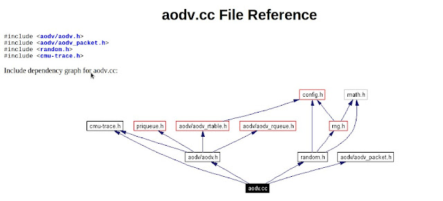
FILE REFERENCE OF AODV.H 


The step by step process happening in AODV network simulation in NS2

1. In the TCL script, when the user configures AODV as a routing protocol by using the command,
$ns node-config -adhocRouting AODV
the pointer moves to the “start” and this “start” moves the pointer to the Command function of AODV protocol.
2. In the Command function, the user can find two timers in the “start
* btimer.handle((Event*) 0);
* htimer.handle((Event*) 0);
3. Let’s consider the case of htimer, the flow points to HelloTimer::handle(Event*) function and the user can see the following lines:

agent -> sendHello();
double interval = MinHelloInterval + ((MaxHelloInterval - Min-HelloInterval) * Random::uniform());
assert(interval -> = 0);
Scheduler::instance().schedule(this, &intr, interval);

These lines are calling the sendHello() function by setting the appropriate interval of Hello Packets.
4. Now, the pointer is in AODV::sendHello() function and the user can see Scheduler::instance().schedule(target , p, 0.0) which will schedule the packets.

5. In the destination node AODV::recv(Packet*p, Handler*) is called, but actually this is done after the node is receiving a packet.

6. AODV::recv(Packet*p, Handler*) function then calls the recvAODV(p) function.

7. Hence, the flow goes to the AODV::recvAODV(Packet *p) function, which will check different packets types and call the respective function.

8. In this example, flow can go to case 
AODVTYPE HELLO:
recvHello(p);
break;
9. Finally, in the recvHello() function, the packet is received.


hope you have got it how to do ...
you can also generate the codes using NSG2

The files related are given below


Displaying a Word or String in an 16x2 LCD with PIC16F877A and MPLAB X

We have seen how to interface an LCD with PIC16F877A  . In this we are printing only a letter in the  LCD , now we are going to Display a string on the LCD  for this following steps are followed


First Create a MPLAB X project as in the steps for  Blinking a LED using MPLAB X , PIC16F877A

And check the  Interfacing LCD with PIC16F877A in MPLAB X  to know how to interface a LCD

Components
1.PIC16F877A micro controller
2. 2x16 LCD Display


we are using the following functions 


  • void delay(unsigned int msec) // Time delay function
  • void lcd_cmd(unsigned char item) // Function to send command to LCD
  • void lcd_data(unsigned char item) // Function to send data to LCD
  • void lcd_data_string(unsigned char *str) // Function to send data to string
  • void lcd(unsigned char str[10])


To display the string in  LCD , just call the below lines in main function


 lcd_cmd(0x01);
  lcd_cmd(0x86);
  lcd("STRING TO DISPLAY");


The functions are defined below 


void delay(unsigned int msec) // Time delay function
{
int i,j ;
for(i=0;i<msec;i++)
  for(j=0;j<1275;j++);
}
void lcd_cmd(unsigned char item) // Function to send command to LCD
{
dataport = item;
rs= 0;
rw=0;
en=1;
delay(1);
en=0;
return;
}
void lcd_data(unsigned char item) // Function to send data to LCD
{
dataport = item;
rs= 1;
rw=0;
en=1;
delay(1);
en=0;
return;
}
void lcd_data_string(unsigned char *str) // Function to send data to string
{
int i=0;
while(str[i]!='\0')
{
  lcd_data(str[i]);
  i++;
  //delay(10);
}
return;
}
void lcd(unsigned char str[10])
{
lcd_cmd(0x38);
lcd_cmd(0x0e);
lcd_data_string(str);
}
 
 
Support : Ebin EPhrem | Ebin Ephrem | #Gabbarism
Copyright © 2011. Services | Embedded Support | Reviews | Virtual Technologys - All Rights Reserved
Template Created by ebinephrem.com Published by Ebin Ephrem
Proudly powered by Blogger