SERVFORU

Latest Post

How to Set Up a Timer in PIC16F877A


We have Three Timers in PIC16F877A , and here we have a look to how to setup the TIMER0 in PIC16F877A using HiTech C programm 


• To set up the timer, one must first disable interrupts so that an interrupt doesn’t occur when the timer expires.
• Then, enable the timer and assign the prescaler to the timer.
• Establish the prescaler value, and finally, load the timer register.
 Whenever the timer expires, the T0IF bit in the INTCON register will be set.
• We must clear this bit, reload the timer register, and then execute the code that is to be done at this time.

In code, the setup portion might look something like:
########################## IN ASSEMBLY PROGRAM ###########################
banksel INTCON
bcf INTCON,T0IE ; Mask timer interrupt
banksel OPTION_REG
bcf OPTION_REG,T0CS ; Enable timer
bcf OPTION_REG,PSA ; Prescaler to timer
bcf OPTION_REG,PS2 ; \
bsf OPTION_REG,PS1 ; >- 1:16 prescale
bsf OPTION_REG,PS0 ; /
movlw D’100’ ; Timer will count
movwf TMR0 ; 156 (256-100) counts

######################## IN HITECH C PROGRAM #######################################
OPTION_REG= 0x0F;
  TMR0=0x0F;
  while(TMR0IF=0);
  TMR0IF=0;
##################################################

• Clearly, the individual bits in the option register could all be set with a single store.
• If we didn’t care about the RB0 interrupt, the weak pullups, or the transition of RA4, then instead of five bit manipulations we could have said:
• movlw B’10000011’ ; Set up prescaler and
• movwf OPTION_REG ; timer

The execution loop might look something like:


main:
    btfss INTCON,T0IF ; Did timer overflow?
    goto main ; No, hang around some more 
    movlw D’100’ ; Timer will count
    movwf TMR0 ; 156 (256-100) counts
    bcf INTCON,T0IF ; reset overflow flag
    call DoCode ; Execute main code
    goto main ; Go back and wait


Using Timers in PIC16F877A


A timer counts pulses of a fixed, known frequency usually the system clock for the processor.Physically, timer is a register whose value is continually increasing to 255, and then it starts all over again: 0, 1, 2, 3,4...255....0,1, 2, 3......etc. 
This incrementing is done in the background of everything a microcontroller does.It is up to programmer to think up a way how he will take advantage of this characteristic for his needs.One of the ways is increasing some variable on each timer overflow.
 – If we know how much time a timer needs to make one complete round, then multiplying the value of a variable by that time will yield the total amount of elapsed time.

PIC16F877A has 3 timer modules, Timer0,Timer1 and Timer2.The device has three readable and writeable hardware timers that can increment automatically each instruction cycle (if no prescaler is used).All timers can cause an interrupt on overflow, and then restart from zero.
• Timer 0
timer/counter with prescale ,an 8-bit timer with an eight bit prescaler, which can make the timer run 2 to 256 times slower than normal

• Timer 1
timer/counter with prescale  a 16-bit timer (two 8-bit registers) with a 1:1 to 1:8 prescaler and some other features. Used by given C code to generate soft timer and sound

• Timer 2
timer only with prescale and postscale , an 8-bit timer with 1:1 to 1:16 prescaler and a 1:1 to 1:16 postscaler It also has a period register.Used by given C code for PWM motor control

Timer 0
  • 8 bit timer/counter with prescaler
  • Readable and writeable
  • 8-bit software programmable prescaler
  • Internal or external clock set
  • Interrupt on overflow from 0xFF to 0x00
  • Edge Select for external clock
use TMR0 in program in hitech-c  MPLAB X 
  OPTION_REG= 0x0F;
  TMR0=0x0F;
     while(TMR0IF=0);
       TMR0IF=0;

TIMER1
  • 16-bit timer/counter with prescaler
  • Readable and writeable
  • 1, 2, 4, 8 programmable prescaler
  • Internal or external clock select
  • External clock can be syn. or asyn.
  • Interrupt on overflow
  • Second crystal permitted

use TMR1 in Hitech C Program 
    T1CON= 0x0F;
    TMR1= 0x0F;
    TMR1ON=1;
        while(TMR1IF=0);
          TMR1IF=0;
          TMR1ON=0;

TIMER2

8-bit timer/counter with prescaler and postscaler
• Readable and writeable
• 1,4 or 16 programmable prescaler
• 4-bit programmable postscaler
• Interrupt on overflow
• Output to port pin

Using Timer2 in Hitech C program
   T2CON= 0x0F;
    TMR2= 0x0F;
    TMR2ON=1;
       while(TMR2IF=0);
             TMR2IF=0;
            TMR2ON=0;


AODV routing Protocol simulation using NS2


The Network Simulator (NS-2) is a most widely used network simulator. It has the capabilities to simulate a range of networks including wired and wireless networks. In this tutorial, we present the implementation of Ad Hoc On-Demand Distance Vector (AODV) Protocol in NS-2.This tutorial is targeted to the novice user who wants to understand the implementation of AODV Protocol in NS-2


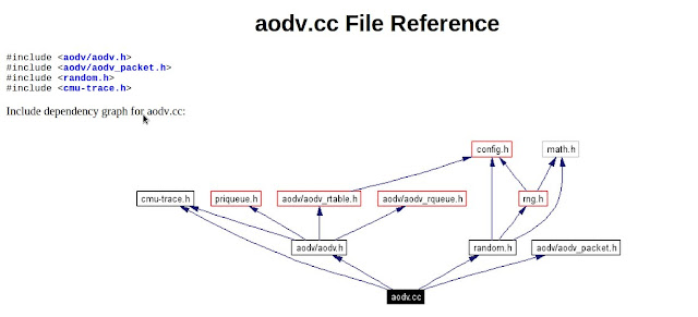
FILE REFERENCE OF AODV.H 


The step by step process happening in AODV network simulation in NS2

1. In the TCL script, when the user configures AODV as a routing protocol by using the command,
$ns node-config -adhocRouting AODV
the pointer moves to the “start” and this “start” moves the pointer to the Command function of AODV protocol.
2. In the Command function, the user can find two timers in the “start
* btimer.handle((Event*) 0);
* htimer.handle((Event*) 0);
3. Let’s consider the case of htimer, the flow points to HelloTimer::handle(Event*) function and the user can see the following lines:

agent -> sendHello();
double interval = MinHelloInterval + ((MaxHelloInterval - Min-HelloInterval) * Random::uniform());
assert(interval -> = 0);
Scheduler::instance().schedule(this, &intr, interval);

These lines are calling the sendHello() function by setting the appropriate interval of Hello Packets.
4. Now, the pointer is in AODV::sendHello() function and the user can see Scheduler::instance().schedule(target , p, 0.0) which will schedule the packets.

5. In the destination node AODV::recv(Packet*p, Handler*) is called, but actually this is done after the node is receiving a packet.

6. AODV::recv(Packet*p, Handler*) function then calls the recvAODV(p) function.

7. Hence, the flow goes to the AODV::recvAODV(Packet *p) function, which will check different packets types and call the respective function.

8. In this example, flow can go to case 
AODVTYPE HELLO:
recvHello(p);
break;
9. Finally, in the recvHello() function, the packet is received.


hope you have got it how to do ...
you can also generate the codes using NSG2

The files related are given below


Displaying a Word or String in an 16x2 LCD with PIC16F877A and MPLAB X

We have seen how to interface an LCD with PIC16F877A  . In this we are printing only a letter in the  LCD , now we are going to Display a string on the LCD  for this following steps are followed


First Create a MPLAB X project as in the steps for  Blinking a LED using MPLAB X , PIC16F877A

And check the  Interfacing LCD with PIC16F877A in MPLAB X  to know how to interface a LCD

Components
1.PIC16F877A micro controller
2. 2x16 LCD Display


we are using the following functions 


  • void delay(unsigned int msec) // Time delay function
  • void lcd_cmd(unsigned char item) // Function to send command to LCD
  • void lcd_data(unsigned char item) // Function to send data to LCD
  • void lcd_data_string(unsigned char *str) // Function to send data to string
  • void lcd(unsigned char str[10])


To display the string in  LCD , just call the below lines in main function


 lcd_cmd(0x01);
  lcd_cmd(0x86);
  lcd("STRING TO DISPLAY");


The functions are defined below 


void delay(unsigned int msec) // Time delay function
{
int i,j ;
for(i=0;i<msec;i++)
  for(j=0;j<1275;j++);
}
void lcd_cmd(unsigned char item) // Function to send command to LCD
{
dataport = item;
rs= 0;
rw=0;
en=1;
delay(1);
en=0;
return;
}
void lcd_data(unsigned char item) // Function to send data to LCD
{
dataport = item;
rs= 1;
rw=0;
en=1;
delay(1);
en=0;
return;
}
void lcd_data_string(unsigned char *str) // Function to send data to string
{
int i=0;
while(str[i]!='\0')
{
  lcd_data(str[i]);
  i++;
  //delay(10);
}
return;
}
void lcd(unsigned char str[10])
{
lcd_cmd(0x38);
lcd_cmd(0x0e);
lcd_data_string(str);
}
 

Counting the number of times pressed of Switch , C program in MPLAB X

In this program we are going to count the number of times a switch pressed,and displaying it on a LCD .. and each time the switch pressed a LED will lighted up.


First create a new project and add a c main file like in the  steps for  Blinking a LED using MPLAB X , PIC16F877A

Components 


1. PIC16F877A micro controller
2. animated LED  
3. A toggle switch
4.16x2 LCD display


Steps in the program

1. define the ports for easy usage 

Defines the control pins of LCD to the 0th,1st and 2nd pin of PORT D
    #define RS RD0
    #define RW RD1
   #define EN RD2
Defines the data port of the  LCD to PORT B
   #define DATA PORTC
Defines switch in the 0th pin of PORT C
   #define S RC0
Defines LED on the 3rd pin of PORT D
   #define L RD3
2. Function declarations .. here we declare 3 functions  and all the 3 functions is for LCD

void LCD_CMD(unsigned int value); //This function is pass the LCD commands
void LCD_DAT(unsigned int value); // this is for pass the DATA to the LCD which is to displayed 
void LCD_INIT(); //this to initialize the LCD
void delay(); // this is to delay the LCD commands 


3. next is main function .. in main function we make 
  •  PORT C as input where we have connected the switch
  •  PORT D as output where we have connected the LED and control pins of LCD
  • PORT B as outout where we have connected DATA pins of LCD
    TRISC  =0x0F;
    TRISD  =0x00;
    TRISB = 0x00;

4. The function LCD_INIT(); is called for initializing the LCD
5. Declared a variable called count, and initialized it to zero
   int count;
   count=0;
6.  we put the LED off 
7. now we are going for a infinite loop by 
    while(1)
    { 
     }
8. In the loop we are checking switch is ON or OFF condition
 if the switch is ON ; LED is on and count is incremented by 1 and display the value of count in LCD 

if the Switch is OFF it wait for the condition when the Switch is ON 

schematic diagram 


full Program
 ###################################################################################
    /*
 * File:   switchcount.c
 * Author: Ebin Ephrem
 
 */

#include<htc.h>
__CONFIG(0x193A);

C
#define RS RD0
#define RW RD1
#define EN RD2
#define DATA PORTB
#define S RC0
#define L RD3

void LCD_CMD(unsigned int value);
void LCD_DAT(unsigned int value);
void LCD_INIT();
void delay();


void main(void)
{
    TRISC  =0x0F;
    TRISD  =0x00;
    TRISB = 0x00;
LCD_INIT();
int count;
count=0;
L=0;

  while(1)
  {
if( S == 1)
       {
    while(S==1);
            L= ~L;
                     count = count+1;
              LCD_CMD(0x01);
        delay ();
    LCD_DAT('0' + (count % 10));
}
       }
 }

void LCD_INIT()
 {
    LCD_CMD(0x01);
    delay ();
    LCD_CMD(0x38);
    delay ();
    LCD_CMD(0x0F);
    delay ();
    LCD_CMD(0x06);
    delay ();
    LCD_CMD(0x0c);
    delay ();

    LCD_CMD(0x80);
    delay ();
}
void LCD_CMD(unsigned int  value)
{
    DATA =  value;
    RS=0;
    RW=0;
    EN=1;
    delay ();
    EN=0;
    delay ();
 }

void LCD_DAT(unsigned int value)
{
    DATA= value ;

    RS=1;
    RW=0;
    EN=1;
    delay ();
    EN=0;
    delay();

}

void delay(void)
{
    int counter = 0;
    for (counter = 0; counter<1000; counter++) {
        ;
    }
}


Remove the mask of passwords in any browser

If we use autofill settings there is a chance to forgot the password , your browser will always block the password box from passersby seeing it by using asterisks. To remove the mask and reveal your password, you just need to do a few things.


Follow the steps:


1. Right-click the password box and select "Inspect Element."This brings up the developer console

2.. On the line that starts with "input type=password

3. Right click and select Edit HTML

4. change the word "password" to "text" ( type="password"  to type="text")


Interfacing Keypad with PIC16F877A in C program using MPLAB X

This tutorial will show you how to read a 4x4 keypad input and write to an alphanumeric LCD interfaced to your PIC micro, it's pretty simple and straight forward.

First create a new project and add a c main file like in the  steps for  Blinking a LED using MPLAB X , PIC16F877A
Components
1.PIC16F877A micro controller
2. 4x4 matrix keypad

initial setup
 supply logic 0 (0V or GND) to all 4 keypad row wires or set the row pins as output
 Supply logic 1 (high voltage) to all 4 keypad coloum wires or set coloums  as input


Steps to read a key from the keypad 
1. Find the Row first, by selecting each row
2. scan the colum  which pressed key is
3 Find the key pressed ,the function findKey() is for this


4. If we have at least one key pressed, then return from keypadread()  will be non zero.


PROGRAM 
#######################################################################
    /*
 * File:   main.c
 * Author: Ebin Ephrem
 
 */


#include<htc.h>

#if defined(WDTE_OFF)
__CONFIG(WDTE_OFF & LVP_OFF);
#elif defined (WDTDIS)
__CONFIG(WDTDIS & LVPDIS);
#endif

char findKey(unsigned int a, unsigned int b);
char readKeyboard();

void main()
{  
   TRISB = 0xF0;

unsigned int re;   
 while(1)
    {
        re=0;
        re= readKeyboard();
    }
}
char readKeyboard()

{
 unsigned int i = 0;
 for(i=0;i<4;i++)
 {
  if(i == 0)
  PORTB = 1;
  else if(i == 1)
  PORTB = 2;
  else if(i == 2)
  PORTB = 4;
  else if(i == 3)
  PORTB = 8;

  if(RB4)
    return findKey(i,0);
  if(RB5)
   return findKey(i,1);
  if(RB6)
   return findKey(i,2);
  if(RB7)
   return findKey(i,3);
 }
 return ' ';
}
char findKey(unsigned int a, unsigned int b) //generating key character 
{

 if(b == 0)
 {
   if(a == 3)
    return '3';
   else if(a == 2)
    return '2';
   else if(a == 1)
    return '1';
   else if(a == 0)
    return '0';
 }
 else if(b == 1)
 {
   if(a == 3)
    return '8';
   else if(a == 2)
    return '7';
   else if(a == 1)
    return '6';
   else if(a == 0)
    return '5';
 }
 else if(b == 2)
 {
   if(a == 3)
    return 'b';
   else if(a == 2)
    return '8';
   else if(a == 1)
    return 'A';
   else if(a == 0)
    return '-';
 }
 else if(b == 3)
 {
   if(a == 3)
    return 'C';
   else if(a == 2)
    return 'U';
   else if(a == 1)
    return 'E';
   else if(a == 0)
    return 'F';
  }
}

######################################################################


you can modify the number of colums and rows for 3x4 keypad , and for the other keypads


Change and Customize Your Google Search Page

Most of us uses www.google.com for searching over internet .. Here is a method to change  image for  your google home page  And make the homepage customised
It's a simple enough feature that we've heard rumors of here and there: Just go to Google.com,Pick any image from Google's Public gallery, your Picasa web album photos, or upload any image from your desktop


For this do following steps ..

1. open your browser and go to picasaweb.google.com 

2. Log in to picasa with your Google ID and Password
3.You can select any albums and select upload in the top 


 4.A new window opens with Drag your Photo here ..or with select photo from your computer
    select the photo that you want to make the homepage image
5.Click OK ..

6.Now go to  www.google.com 
7.Select the link Change background Image in the bottom left corner
8.A new window will appear to select image for  your google home page. Select Your Picasa Web Photos or Your Recent Picks from the side tab on the window
9.Select the Picture that you want to make the google home page image .. 
The google page will load your image as home page .. and njoy... 
you can also set the popular images in the picasa web albums... 
 

Check your Android Device is vulnerable ? How to Make it Secure

Now we heard that a serious security vulnerability was recently discovered that could wipe everything off of some Samsung phones. Although Samsung issued a patch for the Galaxy S III, it turns out it's not just Samsung devices that are affected. Here's how to find out if your Android device is vulnerable.


 Essentially, some phones support special dial codes called USSDs (e.g., dialing *#06# to display the phone's IMEI number). Through malicious links in a website, SMS, NFC beam or QR code, hackers can perform a factory reset on your phone, lock the SIM card, and more—without warning.


Steps to find the your Android device is vulnerable , and make it  secure by using an patch

1 . Go to the link 
 http://dylanreeve.com/phone.php on your phones browser

2.If your phone is vulnerable , you'll immediately see your phone's IMEI number pop up.

If you are vulnerable, you should look for the latest updates for your device.Usually you can go to Settings > About Phone > System Update to check for available updates 

Some browsers (most notably Opera) appear to offer some security by not handling the iframe injection code immediately.

Two apps have also been developed to protect against the vulnerability: Auto-reset blocker andTelStop.

Finally, as always, avoid clicking on any unknown links.


ANALOG TO DIGITAL CONVERTION using PIC16F877A and MPLABX


Many electrical signals around us are Analog in nature. That means a quantity varies directly with some other quantity. The first quantity is mostly voltage while that second quantity can be anything like temperature, pressure, light, force or acceleration.

The PIC16F877A has a built-in Analogue to Digital converter. What ADC does is basically convert an analogue voltage ranging from -Vref to +Vref (usually 0V to 5V) and converts it to a binary value. The ADC on the PIC16F877A has 10-bit resolution and this provides 1024 steps (2^10=1024) which is more than enough for normal applications.


Programming ADC in HI-TECH C for MPLAB

ADC is connect to the PIC CPU by 3 control register and 2 data register. The control registers are used to setup and give commands to the ADC. They also provides the status of ADC. The two data registers holds the 10 bit of converted data. Since each resister in PIC18 is of 8 bits therefore 2 registers are required to hold the 10bit data.
We will develop two functions to support ADC in our projects. One will help initialize the module and other will help us select any of the 13 channels and start the conversion. After the conversion is done it will return us the results.
I am not giving here the description of the control and data registers as they are very clearly explained in PIC18F4520's datasheet on page 223 to 225. I request you to download the datasheet and read the description so that you will have an Idea of what every bit in the registers do. As I told before, ADC is connected to the CPU via three control register and two data registers. The three control registers are :-
  • ADCON0 - Used to select analog input channel,start the conversion, check if the conversion is done and to switch on/off the module.(We use this in ADCRead() function.)

  • ADCON1 - Used to Select Voltage reference, and to configure ports as Analog of digital. (We leave these to defaults)

  • ADCON2 - Used to select ADC data format, Set acquisition time, ADC clock setup (We setup these in ADCInit() function)

First we configure the ADC to our needs in the ADCInit() function.
//Function to Initialise the ADC Module
void ADCInit()
{
   //We use default value for +/- Vref

   //VCFG0=0,VCFG1=0
   //That means +Vref = Vdd (5v) and -Vref=GEN

   //Port Configuration
   //We also use default value here too
   //All ANx channels are Analog

   /*
      ADCON2

      *ADC Result Right Justified.
      *Acquisition Time = 2TAD
      *Conversion Clock = 32 Tosc
   */

   ADCON2=0b10001010;
}


ADCRead function ...


//Function to Read given ADC channel (0-13)
unsigned int ADCRead(unsigned char ch)
{
   if(ch>13) return 0;  //Invalid Channel

   ADCON0=0x00;

   ADCON0=(ch<<2);   //Select ADC Channel

   ADON=1;  //switch on the adc module

   GODONE=1;  //Start conversion

   while(GODONE); //wait for the conversion to finish

   ADON=0;  //switch off adc

   return ADRES;
}


THE PROGRAM IS AVAILABLE ON GITHUB : https://github.com/ebine/
 
 
Support : Ebin EPhrem | Ebin Ephrem | #Gabbarism
Copyright © 2011. Services | Embedded Support | Reviews | Virtual Technologys - All Rights Reserved
Template Created by ebinephrem.com Published by Ebin Ephrem
Proudly powered by Blogger